Accessories
Here you will find an overview of suitable accessories for the selected product series.


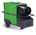
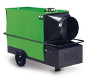
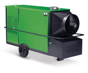
In case of sudden cold or undelayable, scheduled work, the heating systems of the CLK Series bring the necessary heat to wherever it is desired. This makes construction independent of the weather because construction on a deadline means that work may be performed during the cold season. Structures, materials, and workstations must then be protected.
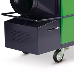
The mobile devices must be in place only during the desired operating time to provide immediate heat when needed without a preheating time.
No other heating system can be used so optimally in glass or plastic film greenhouses as our heating systems. This applies on the one hand for the exact determination of the appropriate device in regard to the size of the greenhouse and the heat output and for the desired operating time on the other. If required, the equipment creates heat without a preheating time as in the case of conventional warm water heating systems or other heating centres. This means a reduction in the energy requirement and thus considerable cost savings.
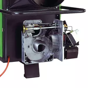
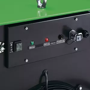
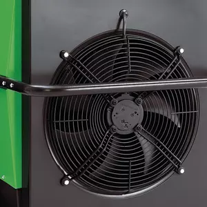
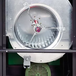
The CLK equipment series can be called a true power driver without exaggeration. These units are the most efficient mobile REMKO heaters with specially optimised sickle fans. Efficient with high delivery pressure for the connection of hot air tubes.
| Variant | CLK 30 | CLK 50 | CLK 70 | CLK 120 | CLK 150 | CLK 80-RV | CLK 170-RV |
|---|---|---|---|---|---|---|---|
| Nominal heat load | 29.0 kW | 46.0 kW | 68.0 kW | 114.0 kW | 150.0 kW | 84.0 kW | 155.0 kW |
| Nominal heat power | 26.5 kW | 42 kW | 62 kW | 105 kW | 138 kW | 77 kW | 144 kW |
| Energy efficiency rating for heating | C | C | B | C | C | C | C |
| Pressure max. | 90 Pa | 145 Pa | 165 Pa | 220 Pa | 260 Pa | 410 Pa | 520 Pa |
| Fuel | EL heating oil/diesel,Biodiesel B7/B10,Biofuel HVO | EL heating oil/diesel,Biodiesel B7/B10,Biofuel HVO | EL heating oil/diesel,Biodiesel B7/B10,Biofuel HVO | EL heating oil/diesel,Biodiesel B7/B10,Biofuel HVO | EL heating oil/diesel,Biodiesel B7/B10,Biofuel HVO | EL heating oil/diesel,Biodiesel B7/B10,Biofuel HVO | EL heating oil/diesel,Biodiesel B7/B10,Biofuel HVO |
Accessories
Here you will find an overview of suitable accessories for the selected product series.
Spare parts
The spare parts search offers all associated spare parts directly for purchase according to the serial number of your device.
Downloads
In the REMKO media portal you have access to an extensive collection of documents and images from our various product areas.