Accessories
Here you will find an overview of suitable accessories for the selected product series.

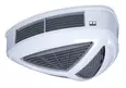
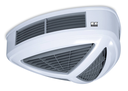
Their flat design and variable technology allows their subtle application, both in low-ceilinged and high-ceilinged rooms. The individually adjustable fins in the upper and lower parts of the housing allow optimum air distribution and thus provide a comfortable room climate. Ease of service and a simple, uncomplicated assembly are the characteristic features of these units. The media connections and the mains cabling can be installed out of sight in the false ceiling. The elegant plastic housing can easily be removed from its bearing elements thanks to the rapid release couplings. The units are fitted as standard with a high-performance condensate pump.
| Variant | PWL 101 H | PWL 102 H | PWL 103 H | PWL 201 H | PWL 202 H | PWL 203 H | PWL 301 H | PWL 302 H | PWL 303 H |
|---|---|---|---|---|---|---|---|---|---|
| Heating capacity at 90/70 and 0°C air intake | 16.5 / 14.7 kW | 26.7 / 24.1 kW | 34.4 / 29.7 kW | 20.8 / 18.7 kW | 36.3 / 32.3 kW | 47.2 / 41.4 kW | 26.9 / 20.3 kW | 44.0 / 31.5 kW | 61.1 / 34.7 kW |
| Heating capacity at 70/50 and 0°C air intake | 12.0 / 10.7 kW | 19.5 / 17.8 kW | 25.4 / 22.0 kW | 14.5 / 13.0 kW | 26.6 / 23.7 kW | 34.5 / 30.4 kW | 18.8 / 14.3 kW | 31.0 / 22.3 kW | 44.8 / 25.6 kW |
| Air flow rate max. | 2030 m³/h | 1960 m³/h | 1885 m³/h | 3110 m³/h | 2900 m³/h | 2850 m³/h | 4300 m³/h | 4150 m³/h | 3900 m³/h |
| Throw | 3.4 m | 3.2 m | 3 m | 7.9 m | 5.8 m | 5 m | 5 m | 7 m | 6.2 m |
| Water volume | 1 l | 1.6 l | 2.5 l | 1 l | 1.8 l | 2.9 l | 1.1 l | 2 l | 3.3 l |
Accessories
Here you will find an overview of suitable accessories for the selected product series.
Spare parts
The spare parts search offers all associated spare parts directly for purchase according to the serial number of your device.